
 ENG
ENG
 English
 русский
 中文简体
中文简体 Español
 Indonesia
Installing telescopic door aluminum tracks demands more than basic DIY knowledge. Whether you are setting up a residential sliding gate or a multi-panel commercial telescopic system, the quality of your track installation determines long-term performance, noise levels, and structural safety. Misaligned rails cause premature wear on rollers, uneven panel travel, and costly callbacks. This guide walks through every phase of the process — from pre-installation assessment to final commissioning — with the technical depth that installers and engineers actually need.
Industry data shows that over 60% of telescopic door failures within the first two years are traced back to improper track installation rather than product defects. Getting the foundation right is everything.
Understanding the Telescopic Door Track System
Before picking up a single tool, it pays to understand how a telescopic door track system is engineered. Unlike a single-panel sliding door, a telescopic system moves multiple panels in a synchronized sequence, each riding its own rail or sharing a multi-channel aluminum extrusion. The telescopic door aluminum profile forms the structural backbone of this system — it must be perfectly level, anchored at the correct height, and free of any twist along its run.
Core Components You Will Work With
Carries the door weight via upper rollers; typically extruded in 6063-T5 aluminum for corrosion resistance and dimensional stability.
Provides lateral stability; keeps panels from swinging outward under wind load. Some profiles integrate this into the extrusion itself.
Steel or nylon-encased bearings that ride inside the track groove; load rating must match panel weight (commonly 80 kg to 400 kg per set).
Bolt-on aluminum or rubber-tipped stops that prevent panels from over-traveling and slamming against the frame at full open or closed position.
Cast or stamped steel brackets that anchor the rail to concrete headers, steel lintels, or timber beams; bracket spacing is typically every 600 mm to 800 mm.
Links multiple panels so they travel in proportion; typically a stainless steel wire rope or toothed polyurethane belt routed through pulleys at each end of the rail.
How Panel Synchronization Works
In a two-panel telescopic system, the drive panel (directly connected to the motor or manual operator) pulls the second panel at twice the speed via a 2:1 cable ratio. A three-panel system uses a 3:1 ratio. This mechanical multiplication means the outermost panel always finishes stacking at the same moment as the drive panel reaches its travel limit. Any slack or stretch in the synchronization cable throws this ratio off, causing panels to collide mid-travel — one of the most common damage scenarios in telescopic systems.
Pre-Installation Planning and Site Assessment
Successful telescopic gate rail installation begins well before the first anchor bolt is drilled. A thorough site assessment prevents the most expensive mistakes.
Structural Header Evaluation
The header — the beam or structure above the opening — must carry the full dynamic load of the door system plus wind loads. For a typical 4-meter wide, 2-meter tall aluminum telescopic door with two 40 kg panels, the header must handle at minimum a distributed load of 1.2 kN/m, plus a safety factor of 1.5. Concrete lintels of 150 mm x 150 mm cross-section or steel RHS (Rectangular Hollow Section) of 100 mm x 50 mm x 4 mm wall are commonly specified. If in doubt, commission a structural engineer's assessment before proceeding.
Opening Width and Stack Space Calculation
| Opening Width | Number of Panels | Minimum Stack Space Required | Recommended Rail Overhang |
|---|---|---|---|
| Up to 3 m | 2 panels | 55% of opening width | 150 mm beyond stack |
| 3 m to 5 m | 2 to 3 panels | 50% of opening width | 200 mm beyond stack |
| 5 m to 8 m | 3 to 4 panels | 45% of opening width | 250 mm beyond stack |
| Over 8 m | 4+ panels | 40% of opening width | 300 mm beyond stack |
Stack space is the clear wall run beside the opening where panels stack when fully open. Underestimating this dimension is a project-stopping error discovered too late.
Floor Level Tolerance Check
Use a laser level or a long spirit level (minimum 1.2 m) to check the floor across the full door travel path. A tolerance of plus or minus 3 mm over any 2-meter run is acceptable for most bottom guide systems. Beyond this, the floor must be ground down or leveled with a self-leveling compound before the bottom channel is fitted. Never shim bottom guides with folded steel — shims compress over time and introduce the very misalignment you are trying to prevent.
Tool and Material Checklist
- Rotary hammer drill with SDS-Plus bits (8 mm and 12 mm)
- Laser level or optical level with tripod
- Digital torque wrench (10 to 80 Nm range)
- Aluminum-compatible cutting blade or cold saw
- Steel tape measure (minimum 5 m)
- String line and chalk line
- Hex key set and combination spanners
- Thread-locking compound (medium strength)
- Anti-corrosion lubricant for roller bearings
- Protective gloves and safety glasses
Step-by-Step Telescopic Gate Rail Installation
With the site fully assessed and materials prepared, you can begin the physical installation. Follow this sequence precisely — skipping steps or reversing the order creates compounding alignment errors that are difficult to resolve once panels are hung.
Step 1: Mark the Rail Centerline and Height
Snap a chalk line across the header at the rail mounting height. The top of the rail should sit at least 50 mm above the top of the door panels to allow for roller adjustment range. Use your laser level to project a perfectly horizontal line across the full rail run, including the stack zone. Mark bracket positions at the specified spacing — typically every 600 mm — starting from the fixed end (the jamb side where panels stack when closed).
Step 2: Install End Bracket Anchors First
Drill the end bracket positions first. For concrete headers, use M10 x 75 mm sleeve anchors torqued to 35 Nm. For steel lintels, use M10 hex-head bolts with spring washers. Do not install intermediate brackets yet — the end brackets establish your datum points for aligning the entire rail. Check both end brackets with the laser level before moving on.
Rail installation sequence — follow this order to avoid compounding misalignment
Step 3: Hang the Aluminum Track Rail
Lift the rail into position with a helper or a temporary support jig — do not attempt this solo on runs over 2 meters. Rest the rail in the end bracket saddles and hand-tighten the clamping bolts just enough to allow fine adjustment. With your laser level running, adjust the rail until it sits within 1 mm of the reference line along its full length. A straight aluminum extrusion will cooperate with fine shimming at the bracket saddle — use aluminum shim stock only, not plastic, as plastic creeps under load.
Step 4: Fit and Tighten Intermediate Brackets
Working from the fixed end toward the open end, drill and fit each intermediate bracket. Pull the bracket up snug to the underside of the rail before drilling — do not let the rail deflect downward to meet a poorly positioned bracket. Once all brackets are in place and the rail alignment is re-confirmed with the laser, tighten all bolts in sequence from center outward. Apply medium-strength thread-locking compound to all threaded fasteners that pass into aluminum, as vibration from door cycling will loosen untreated fasteners within weeks.
Step 5: Install the Bottom Guide Channel
The bottom channel governs lateral stability. Snap a chalk line on the floor directly below the center of the top rail — not below the rail face. Use the laser plumb function to transfer the top rail centerline to the floor. Cut the bottom channel to length with an aluminum-compatible blade, leaving a 5 mm gap at each end to allow for thermal expansion. Anchor the channel to the floor at 500 mm intervals using M8 x 50 mm concrete anchors. Check that the channel is parallel to the top rail using a plumb bob or laser plumb at both ends and the midpoint.
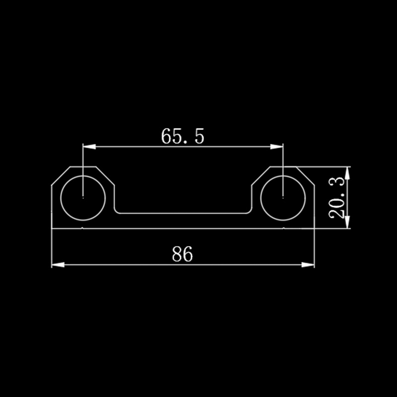
Step 6: Fit Rollers to Door Panels
Attach roller assemblies to the top of each panel according to the manufacturer's specification. For most aluminum door panel profiles, rollers mount in pairs at each stile (vertical edge) with a center-to-center distance of 80 mm to 120 mm. Roller height is adjusted by a threaded stem — set all rollers to mid-range before hanging the panels so you have adjustment range in both directions. Apply a light film of anti-corrosion grease to the roller axles but keep it away from the bearing track groove.
Step 7: Hang the Panels and Set Running Height
Starting with the innermost panel (the one that stacks closest to the wall), lift each panel and engage its rollers into the top track groove. Slide the panel along the rail and check that it runs freely without binding. Use the roller height adjustment to set a consistent 5 mm clearance between the bottom of the panel and the floor across its full travel. Repeat for each panel, working from innermost to outermost.
Step 8: Install and Tension the Synchronization Cable
Thread the stainless steel synchronization wire through the pulley system according to the design drawing — the route depends on whether your system is a 2:1 or 3:1 configuration. Clamp the fixed end of the cable at the anchor point, then pull the cable taut and clamp the adjustable end using the barrel adjuster. Correct tension is achieved when the cable deflects no more than 10 mm under a light hand squeeze at the midpoint. Over-tensioning forces excessive load onto the pulley bearings; under-tensioning creates slack that causes panel collision during acceleration.
Step 9: Fit End Stops and Test Travel
Install end stops at both the fully open and fully closed positions. Position each stop so the panel reaches its intended limit position with 5 mm to 8 mm of deceleration buffer before contact. With stops in place, manually cycle the door through its full travel five times. The panels should move smoothly, stack neatly, and return to closed position without any rubbing against each other or the frame.
Sliding Door Track Alignment: Critical Tolerances
Track alignment is the single most consequential factor in telescopic door longevity. Aluminum door profile assembly errors that fall outside the tolerances below will cause accelerated wear, noise, and eventual failure of rollers or the rail itself.
Check at every bracket position and at mid-span between brackets using a digital level or laser. Any reading over 1 mm requires re-shimming before proceeding.
A bowed rail forces rollers to fight sideways as they travel, creating noise and accelerated flange wear. Straighten the extrusion before installation if it exceeds this tolerance.
A tilted rail causes all rollers to bear on one flange only, reducing effective load capacity by up to 40% and causing premature groove wear.
This gap allows the panel to clear floor unevenness without scraping while keeping the bottom guide roller engaged in the channel. Check at open, mid-travel, and closed positions.
Using a Laser Level for Alignment Verification
A rotary laser level set to self-leveling mode is the most reliable tool for verifying rail alignment. Mount the tripod at the midpoint of the rail run, project the beam along the rail, and read the deviation at each bracket using a laser staff or a simple target card. Record measurements in a table and calculate the maximum deviation across the run. This record is valuable documentation if warranty questions arise later.
Common Alignment Errors and Their Causes
| Symptom | Most Likely Cause | Correction |
|---|---|---|
| Panel binds at one point in travel | Local rail bow or high bracket pulling rail out of line | Re-shim bracket at that position; check rail straightness |
| Panels drift open under wind | Rail tilted toward open direction (not level) | Re-level rail; add anti-drift latch or bottom pin |
| Scraping noise from bottom | Bottom guide channel not parallel to top rail | Re-align bottom channel using laser plumb |
| Rollers jump out of groove | Rail twist or insufficient roller flange depth | Check rail for twist; upgrade to deeper-groove roller |
| Panels collide mid-travel | Synchronization cable slack or wrong ratio | Re-tension cable; verify pulley configuration |
| Excessive vibration at speed | Loose bracket fasteners or roller bearing wear | Re-torque all fasteners; replace worn roller bearings |
Aluminum Door Profile Assembly: Key Technical Details
The quality of aluminum door profile assembly directly affects sealing, panel rigidity, and the long-term integrity of the entire door system. This phase covers the work done on the panel frames themselves before and during installation.
Cutting Aluminum Extrusions to Length
Always use a cold saw or a fine-tooth carbide blade rated for non-ferrous metals. Abrasive cut-off wheels generate heat that retempers the aluminum surface and leaves a rough edge prone to cracking. Set the fence stop to cut all matching stiles and rails to exactly the same length — a 0.5 mm length discrepancy between paired stiles causes the panel frame to rack (become non-square), preventing the mitered corners from closing fully.
After cutting, deburr all cut faces with a flat file and wipe the joint area with isopropyl alcohol before applying structural glazing tape or corner key adhesive. Aluminum swarf (filings) trapped in a corner key joint will crack the extrusion over time as the joint expands and contracts thermally.
Corner Key Assembly
Aluminum door frames are typically assembled using cast or extruded aluminum corner keys that insert into the hollow chambers of the profile and are then crimped or screwed in place. The crimping method uses a dedicated crimping tool to deform the outer wall of the extrusion into the key — this produces a permanent, rattle-free joint. The screw method uses self-tapping screws driven into pre-drilled pilot holes; it is reversible but marginally less rigid. For telescopic doors subject to frequent cycling, crimped corners outperform screw-fixed corners by a significant margin in fatigue resistance.
Glazing and Infill Panel Retention
Once the frame is assembled, the glazing or solid infill panel is retained by a snap-in glazing bead — a thin co-extruded aluminum strip with a flexible rubber toe that clips into a groove on the inner face of the frame profile. Always glaze from the interior side of the door so that wind pressure pushes the glazing bead tighter into its groove rather than forcing it out. Apply a continuous bead of silicone sealant in the glazing pocket before inserting the glass or panel to prevent water ingress at the bead-to-frame interface.
Hardware Mortising and Pre-Drilling
All lock mortises, handle backsets, and hinge recesses should be machined or routed before the panel is hung. Working on a hung panel is imprecise and dangerous. Use a drill press or a router table with an end stop for repeatable, square mortises. The lock body must sit flush with the panel face — a proud lock body prevents the panel from seating against the astragal seal and leaves a visible gap that compromises both security and weatherproofing.
Hardware Guide Installation for Telescopic Systems
Hardware guide installation in a telescopic door context includes more components than a standard sliding door — there are pulleys, cable anchors, drive brackets, and guide rollers that all require careful placement and adjustment.
Pulley Selection and Mounting
Pulleys for the synchronization cable must be rated for the cable diameter and the expected operating load. A 3 mm stainless steel cable typically pairs with a pulley sheave diameter of at least 30 mm — smaller sheaves cause the cable to fatigue rapidly at the bend point. Mount pulleys squarely to their bracket face using the full complement of bolt holes provided; a pulley mounted on only two of its four holes will rotate under load and progressively misalign the cable path.
Drive Bracket and Motor Plate Positioning
The motor plate must be mounted so the drive shaft is perfectly parallel to the top rail. A drive shaft angled even 2 degrees off-parallel creates a lateral force on the drive bracket that will cause it to creep along the rail over thousands of cycles. Most motor mounting plates have slotted holes for fine adjustment — use these to dial in parallelism with a digital angle gauge before final tightening.
Setting the Limit Switches
Electromechanical or magnetic limit switches define the exact stop points for motorized systems. Set the open limit first — cycle the door to the position where the outermost panel edge aligns with the face of the jamb, then trigger and lock the limit. Set the close limit so the leading edge of the drive panel compresses the astragal seal by 3 mm to 5 mm — enough for a weathertight closure without straining the motor. Test both limits by running three full automatic cycles and confirming the stop positions do not drift.
Anti-Lift Device Installation
Telescopic doors in exposed locations require anti-lift devices — typically a bolt-on hook bracket that engages under the top flange of the rail, preventing the panel from being lifted out of the track by wind uplift or deliberate force. Anti-lift brackets are installed on both stiles of each panel, positioned 100 mm below the top roller. The clearance between the hook and the rail flange should be 1 mm to 2 mm — tight enough to prevent lifting but loose enough not to drag during normal operation.
Thermal Expansion Management in Aluminum Track Systems
Aluminum expands at approximately 23 micrometers per meter per degree Celsius. A 6-meter aluminum track rail in a climate with a 50-degree Celsius seasonal temperature range will expand and contract by nearly 7 mm across the year. Ignoring this movement causes rails to buckle in summer and gap at joints in winter.
Expansion Joint Placement
For track runs over 4 meters, at least one expansion joint must be incorporated. An expansion joint is a deliberate slip joint where two rail sections overlap inside a sleeve but are not rigidly bolted together — one bolt hole is slotted to allow the rail end to slide. Position expansion joints at the midpoint of the run or at the location of a fixed structural column where the building itself acts as an anchor point. Mark expansion joints clearly in your as-built documentation so future technicians do not mistakenly tighten the slip bolt.
Gap Allowances at Rail Ends
Always leave a minimum 5 mm gap between the cut end of the rail and any abutting surface — masonry, column face, or end cover plate. Seal this gap with a flexible silicone bead, not a rigid filler. The same 5 mm rule applies to the bottom channel, where the channel end must not be caulked tight to the floor finish or expansion will crack the floor tile or the channel anchor points.
Post-Installation Inspection and Commissioning
A professional installation is only complete after a structured commissioning process that verifies every parameter is within specification and the system is safe for end-user operation.
Commissioning Checklist
- Verify all fastener torques against specification using a calibrated torque wrench and mark each confirmed fastener with a paint pen.
- Confirm rail level deviation is within 1 mm across the full run using the laser level, and record measurements.
- Check synchronization cable tension at midpoint — 10 mm maximum deflection under hand pressure.
- Cycle the door manually ten times and confirm no binding, scraping, or roller disengagement occurs.
- For motorized systems, run ten automatic cycles and confirm limit switches engage at consistent positions (within 2 mm variation).
- Test anti-lift devices by attempting to lift each panel at the anti-lift bracket — no lift-out should be possible.
- Inspect all end stops and buffers for secure mounting and confirm buffer contact before bolt contact at travel limits.
- Apply a thin film of approved track lubricant (PTFE-based spray for aluminum tracks — do not use grease, which attracts grit) to the full length of the rail groove.
- Check weatherstrip seals around the perimeter for continuous, even compression when the door is closed.
- Photograph the completed installation for as-built records and warranty documentation.
Handover to End User
Document the recommended maintenance schedule: quarterly lubrication of track and rollers, annual inspection of fastener torques, and annual tension check on the synchronization cable. End users who understand this schedule will not be surprised when maintenance costs arise, and they will report early symptoms of wear before small problems become expensive failures.
Maintenance Schedule and Long-Term Performance
Aluminum telescopic door systems are designed for decades of operation, but only when maintained on a structured schedule. The following intervals are based on typical residential usage of 15 to 20 cycles per day. Commercial applications with 50 or more cycles per day should halve all maintenance intervals.
| Interval | Task | Tool Required | Acceptance Criterion |
|---|---|---|---|
| Monthly | Visual inspection of rollers and track for debris or damage | Flashlight | No visible cracking, excessive wear marks, or foreign objects in groove |
| Quarterly | Apply PTFE lubricant to track groove and roller axles | PTFE spray can | Even film coverage, no excess pooling |
| 6 Months | Check and re-tension synchronization cable | Barrel adjuster tool | Less than 10 mm mid-span deflection |
| Annual | Inspect all fasteners and re-torque as needed | Calibrated torque wrench | All bolts at specification torque |
| Annual | Inspect and replace weatherstrip seals if compressed flat | Utility knife, sealant gun | Seals recover to original thickness within 24 hours of door opening |
| 2 Years | Replace roller bearings as preventive maintenance | Roller removal tool, torque wrench | Panels run silently and without play after replacement |
A well-maintained telescopic door aluminum profile system installed on a correctly assessed and prepared header can exceed 500,000 operating cycles before requiring major component replacement — equivalent to more than 60 years of residential service.
Frequently Asked Questions
Q1: What is the minimum header depth required to support a telescopic door track?
The minimum header depth depends on the door weight and span. As a general guideline, a reinforced concrete lintel of at least 150 mm depth is required for spans up to 4 meters and door weights up to 200 kg. For spans beyond 4 meters or heavier panels, an engineered steel beam is typically specified. Always consult a structural engineer before relying on any existing header that was not designed with a telescopic door load in mind.
Q2: Can I install a telescopic door track on a timber frame wall?
Yes, but only when the timber header is sized correctly and the track brackets are anchored into solid timber members — not into plywood sheathing or insulation. Use minimum M10 lag screws at least 80 mm into solid timber, and fit a continuous backing plate of at least 6 mm steel between the bracket and the timber to distribute the point loads. Timber that shows any signs of moisture damage, splitting, or insect attack must be replaced before installation.
Q3: How do I know if my synchronization cable tension is correct?
With the door panels held in their mid-travel position, press the cable lightly with two fingers at the midpoint of its run. Correct tension produces no more than 10 mm of deflection under moderate hand pressure — roughly the force required to compress a sponge. If the cable deflects significantly more, use the barrel adjuster to increase tension in half-turn increments until the correct deflection is reached. Over-tightening causes the cable to transmit excessive load to the pulley bearings and shorten their service life.
Q4: What lubricant should be used on aluminum track rails?
Use a dry PTFE (polytetrafluoroethylene) spray lubricant. PTFE leaves a dry film that does not attract grit or dust, which is critical in exposed locations such as driveways or warehouse doors where abrasive particles would otherwise become embedded in a grease film and act as lapping compound against the roller and track surfaces. Avoid petroleum-based oils and silicone sprays in track grooves — petroleum oils degrade rubber seals, and silicone sprays leave a residue that becomes tacky and collects debris over time.
Q5: How do I correct a telescopic door that sags on one side after installation?
Sagging on one side is almost always caused by unequal roller height settings across the width of the panel. Access the roller height adjustment screws at the top of the sagging stile and raise them in small increments — typically a quarter turn at a time — until the bottom edge of the panel is parallel to the floor across its full width. If adjustment screws are already at maximum travel and the panel still sags, check whether the rail has deflected downward at that bracket position due to a loose or under-shimmed mounting.
Q6: Is it necessary to seal the ends of cut aluminum extrusions?
Yes, for exterior or coastal applications. The hollow chambers of an aluminum extrusion can collect condensation and corrosive moisture, which reacts with the aluminum over time, particularly in salt-laden air environments. Press a close-fitting plastic or rubber end cap into each open chamber at cut ends and seal the perimeter with a UV-stable silicone. This takes less than five minutes per cut face and can prevent cosmetically damaging white corrosion deposits that are otherwise very difficult to remove once established.
Q7: What is the difference between a top-hung and a bottom-rolling telescopic door track system?
In a top-hung system, the full weight of the panels is carried by rollers running in the top rail, and the bottom guide channel only provides lateral stability without bearing significant vertical load. This is the predominant configuration for telescopic doors because it keeps the load path in the robust header structure and keeps the floor channel lightweight and low-profile. In a bottom-rolling system, the panels ride on floor-level rollers and the top track provides lateral guidance only. Bottom-rolling systems are typically used for very heavy industrial panels where a top-hung track would require an impractically deep header beam, but they are more susceptible to floor debris interference and require more frequent maintenance of the floor-level rolling components.


